From residual waste.
To reliable power.
A modular waste-to-energy project: municipal waste sorting, refuse-derived fuel production and
gasification-based electricity generation, developed by ABEX Green Energy.
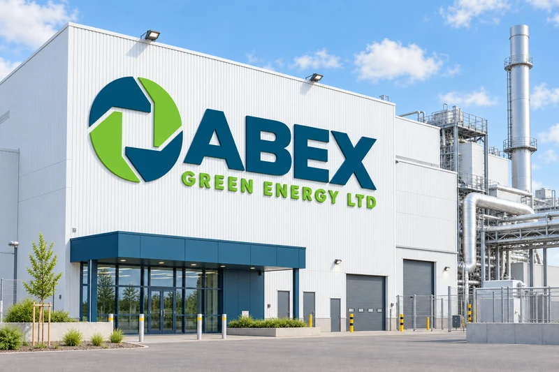 Conceptual visualisation · not an operating facility
Design targets, not an operating record. Capacity, throughput and fuel balance will be reconciled in the full engineering design.
Recover materials. Prepare residual waste for energy.
The proposed sorting stations separate recoverable materials from municipal waste and prepare the combustible residual fraction as fuel for the power plant.
Mixed waste arrives
Municipal waste from local towns is delivered to the station.
Mechanical sorting
The waste stream is sorted by size, density and material.
Recyclables removed
Recyclables and inert material are separated and sent on.
Fuel is made
The combustible fraction becomes refuse-derived fuel (RDF) at 8–15 MJ/kg.
Local fuel. Round-the-clock power.
The fuel prepared at the sorting station is converted into gas, and the gas into electricity: a continuous process that runs day and night, independent of weather.
Refuse-derived fuel
The fuel specification will define calorific value, moisture and contaminants. Classification and testing are to be confirmed during engineering.
Gasification
In a low-oxygen reactor the fuel is converted into a combustible gas rather than burned directly. Ash is collected for treatment.
Electricity
The gas feeds power generation units. The design target is up to 10 MW of installed electrical capacity; net output, availability and grid connection are subject to engineering.
The project materials reference Bulgarian utility model BG № 4983 U1 for gasification and ash vitrification. Technical scope and rights are subject to verification.
Technical parameters ↓Emission control is part of the design.
The project materials include indicative flue-gas results. The laboratory report and reference conditions are still required before compliance can be assessed.
Controlled gasification
Gasification, gas cleaning and controlled energy recovery are designed as one process. Performance must be verified for the selected fuel and operating conditions.
Residuals and environmental assessment
Potential climate benefits require a lifecycle assessment. Ash treatment and vitrification are later-stage options, subject to full technical design and testing.
Reliable supply. Where it is needed.
The model fits regions where three things coincide: a power system losing baseload capacity, residual waste that needs a destination other than landfill, and an industrial site with a grid connection.
Managed decline of baseload capacity
A modular, dispatchable plant can complement solar and wind where dependable capacity is needed. Availability and maintenance must be included in the energy plan.
A destination for residual waste
A sorting station can provide a local route for residual municipal waste after recovery of recyclable materials. Supply, acceptance criteria and permits need to be agreed.
Industrial site with grid access
An existing industrial site or former power plant with a grid connection, and road, rail or river access to regional fuel suppliers. Brownfield sites are preferred.
Gasification technology.
Modular by design.
The plant is assembled from factory-built modules, each under 5 MW, so the same configuration can be repeated in other regions.
The proposed RDF feed range is 8–15 MJ/kg. Any use of tyre-derived fuel requires an agreed blending specification, fuel testing and the applicable permits.
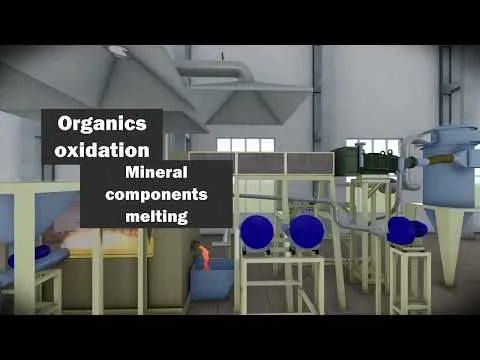
Technical parameters are subject to engineering validation and are confirmed in response to a qualified enquiry.
Baseload that fits around other businesses.
The plant generates electricity continuously and, with waste-heat recovery, usable heat. That profile complements three kinds of energy user.
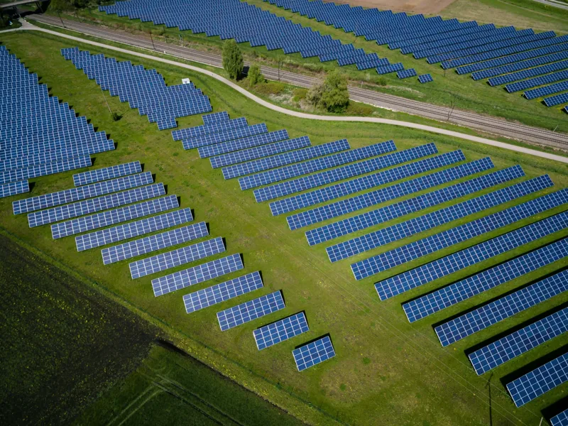
Heat-based applications depend on waste-heat recovery, which follows the full technical design. Electricity supply is available from the start of power generation.
Partner with the plant ↓Open for partners.
Co-investment
Equity participation at project-company level, including contribution of land or capital.
Discuss ↗Fuel supply
Producers of refuse-derived fuel, tyre recyclers and waste operators in the plant's region.
Discuss ↗Power off-take
Long-term purchase of 24-hour electricity, including portfolios that balance solar output.
Discuss ↗Engineering and equipment
Construction contractors, equipment suppliers and design firms for each site.
Discuss ↗Let's discuss the project.
Tell us about your company, your region and your interest in the waste-to-energy model. Technical parameters, scope and participation terms are provided in response to a qualified enquiry.
LOI@abex.bg ↗Your details are used to handle your enquiry. Privacy notice.